Recently, I’ve been itching for a fun hardware project to work on. Part of that spark came when I was looking through some of my old college projects, in particular the Track Independent Train Mapping and Identification project that was the focus of the Embedded System Design course I took at Virginia Tech.
I worked on this project in a small team, and I’m sure each of the members would agree that we learned more about engineering in that single class than in any other (and probably a few of the others combined). This was very much a practical project, which meant we had to design and build our embedded devices and write the software to make them work. I’ve written up a quick summary of that project to inaugurate the blog.
The Task
Our task was to create a system that was capable of identifying the engine and freight cars in a model train as well as “mapping” the model train track. One of the key requirements of the design was that our train had to be capable of mapping the track without external assistance, in other words we couldn’t have sensors along the track for the purpose of mapping (however, this was permitted for recognizing the train cars). We wrote embedded software for Microchip PIC processors and then integrated these PICs into custom fabricated circuit boards we designed. We also developed software for a real time operating system running on a Spartan 3E board. All the major components of the system communicated via an I2C bus.
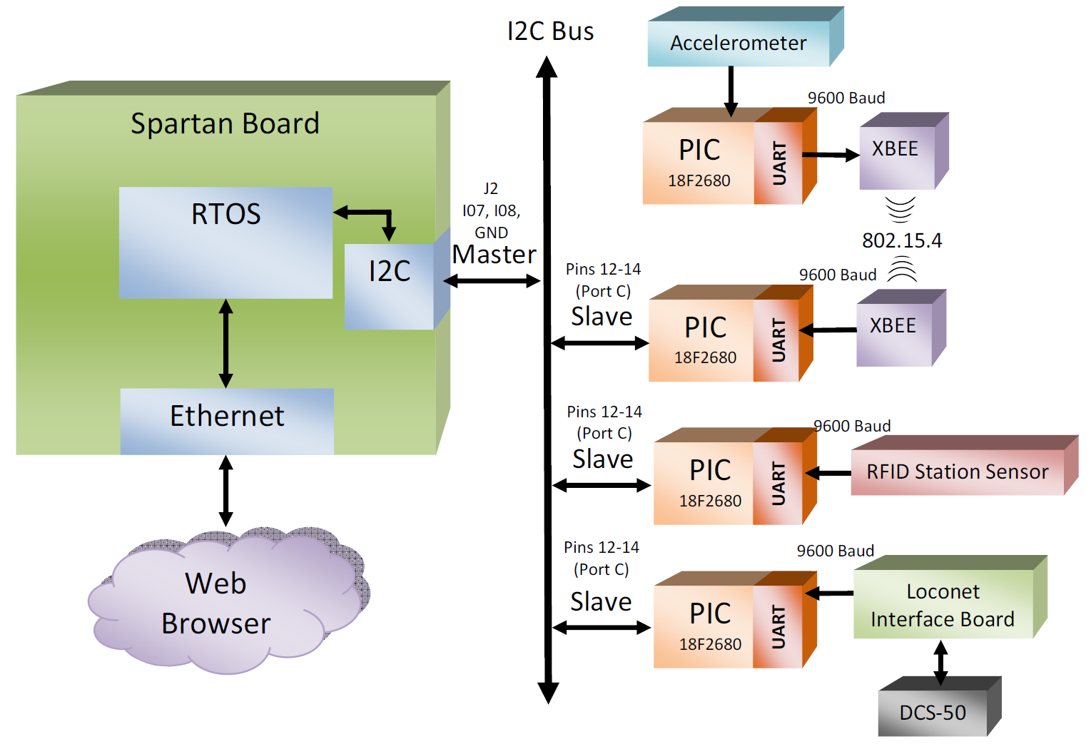 Embedded system block diagram
The Implementation
For identifying the train cars, we did some research as to how trains are identified in the real world. Major train operators use radio-frequency identification or RFID to keep track of containers on train carriages. We copied this paradigm, building our identification system around RFID tags mounted on the cars of the model train. These tags were read by an ID-12 RFID tag reader integrated into the RFID board adjacent to the track (representing a train station). By comparing the identification number burned into the card with a database of numbers stored on the RFID board’s PIC, this board was able to identify the train cars and transmit this information upstream to the Spartan board.
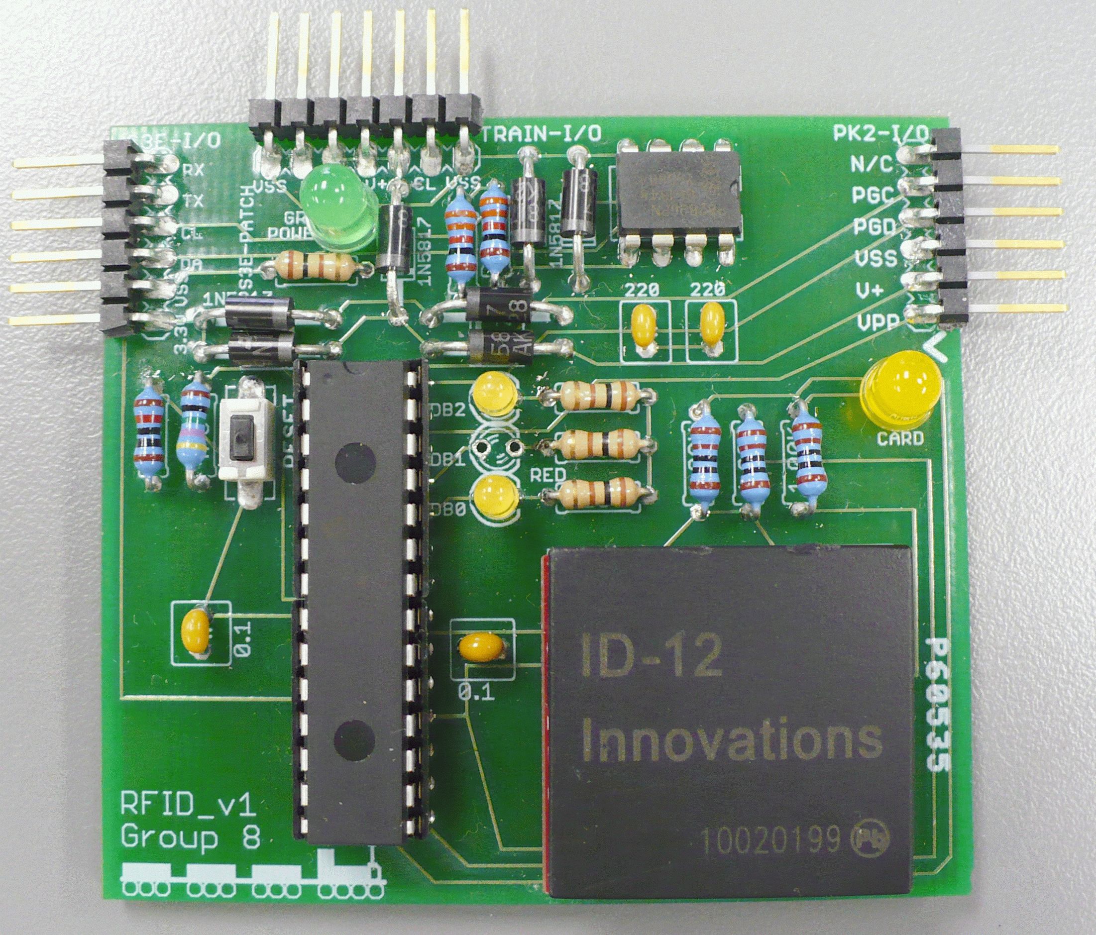 RFID board
For mapping the track we bounded the problem into two parts: detecting straight track vs. curved track and detecting bumps in the rails. The track type was mapped by measuring the slight differences in g-force experienced by the train as it traveled on a straight portion of the track vs. a curved portion. The bumps were detected by recording sharp g-force changes in the Z-axis. We used an accelerometer on the train to measure these forces, processed the raw analog output from this accelerometer with a PIC, and transmitted the data wirelessly via XBee radios integrated into the train board and a base station board near the track.
We became aware of a lot of noise in the analog signals being read by the the PIC processor. This was because the capacitor in the PIC’s analog to digital converter circuitry was having trouble being driven by the low amount of current emanating from the accelerometer. We solved this problem with a compromise; for our Y-axis channel, which was being used to measure turns we implemented a low-pass filter, at the expense of a longer slew rate. This was necessary as we needed a very accurate value, however did not need it to change all that quickly to detect corners (which lasted for several seconds). For our Z-axis channel we just read the raw noissy accelerometer data. Since this channel was only needed for bumps this was the best solution as we needed close to instantaneous response to detect the bumps and the high magnitude changes were easy to pick out even with the noisy signal.
We determined that if we were to do it again, we probably would’ve found a different solution for the track mapping piece. The accelerometer worked great for detecting bumps, but wasn’t anywhere near ideal for mapping the curves due to the very small g-forces they generated which led to difficulty calibrating the accelerometer to recognize them consistently.
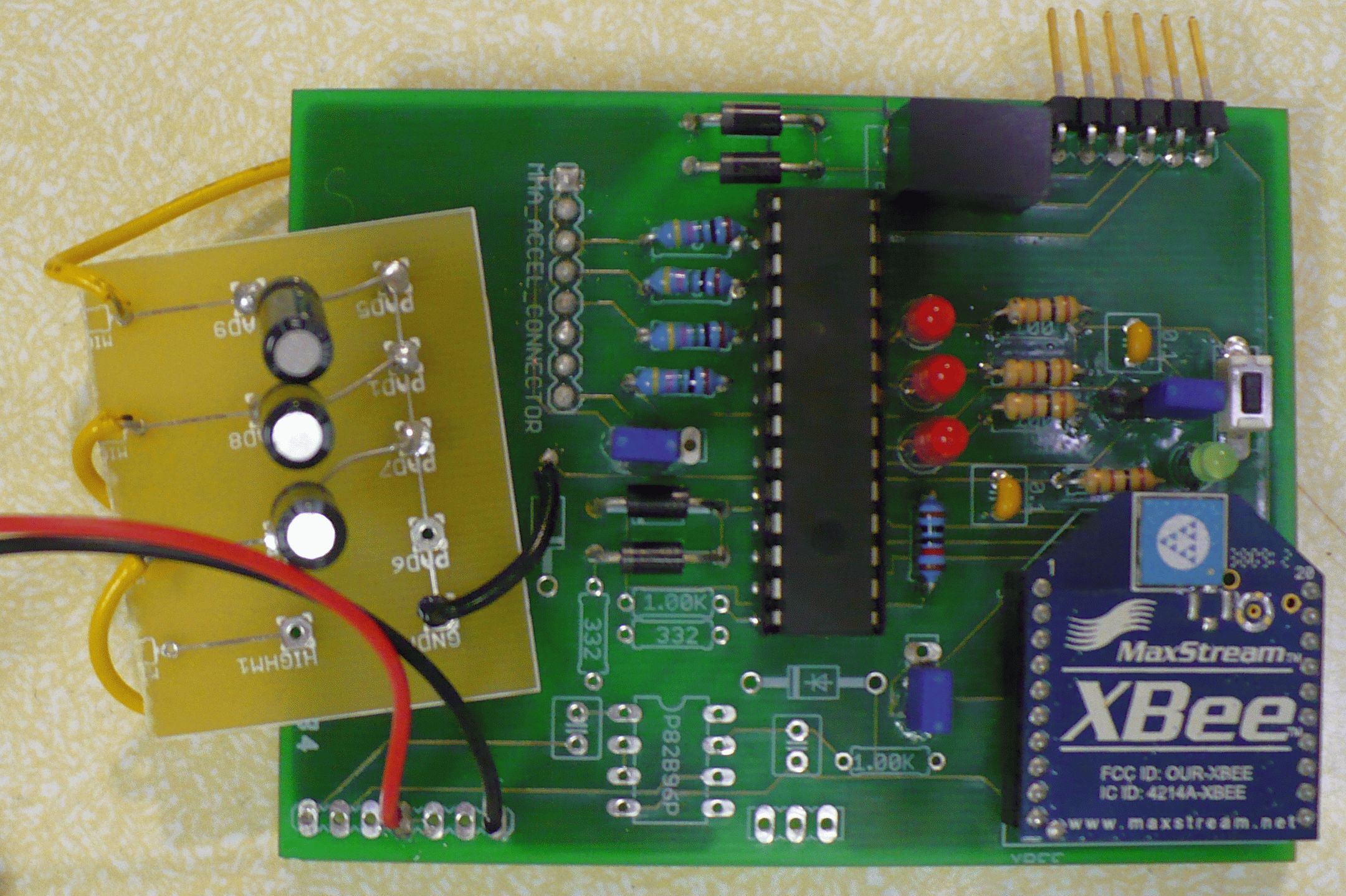 Accelerometer board top with low-pass filter
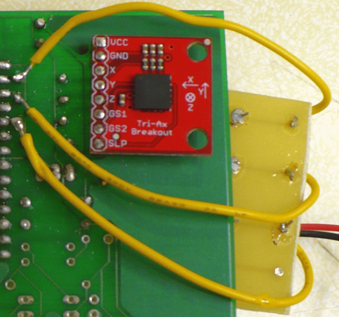 Accelerometer board bottom
The data from the RFID board and the XBee wireless base station board was communicated to the Spartan 3E board via the I2C bus. The Spartan code polled the other devices for their data over I2C on a periodic timer, analyze and interpreted this data, and displayed it on a web server. The card data from the RFID board in the station, the accelerometer data from the train, and data from the Loconet train controller itself were all analyzed and displayed.
We based the algorithm used to analyze the turn status of the accelerometer on hard-coded constants, however this was not consistently accurate for all turns as even a slight inconsistency in the accelerometer’s placement on the train car, or tilt of the car itself could throw this off. It would have been better to use a calibration algorithm that based the definitions of a right or left turn off of the initial accelerometer state, as opposed to a hard-coded value.
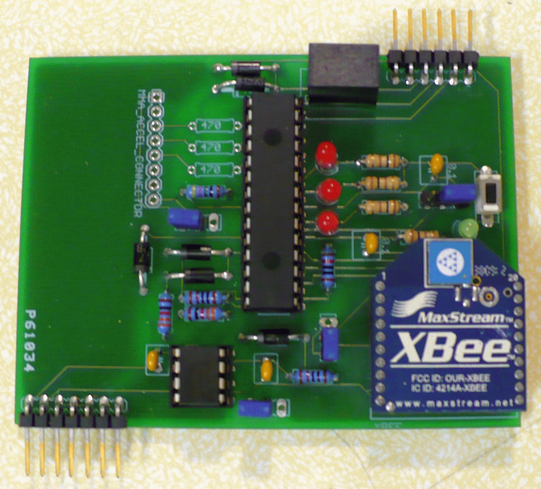 XBee wireless base station board
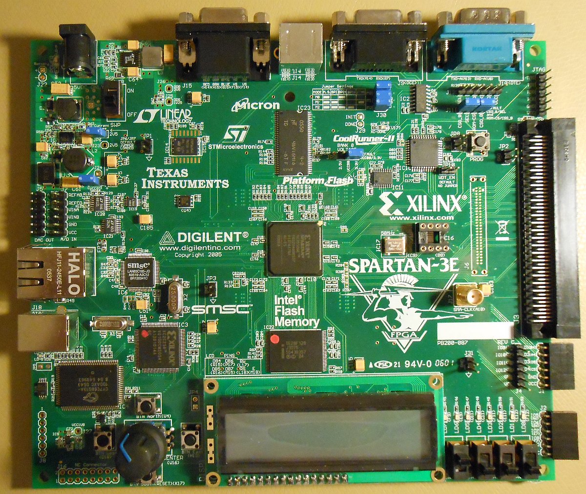 Spartan 3E board
My principal responsibilities in this project were the design and development of the RFID board and the real-time software for the Spartan 3E board. The RFID board was such a rewarding component to work on since I had to work through all components of the design, everything from design of the board to component sourcing to assembly to software design and development to integration and test. It was very rewarding to hold the tangible device at the end of the project and have it work flawlessly with the rest of the system.
The entire project was a real trial by fire but was extremely rewarding to see it (mostly) work properly to solve the problem.
Also, what project would be complete without a goofy video documenting our exploits? We made one of those too.
>> Home