I’m a huge fan of themed entertainment, especially the Disney parks. Theme park rides are some of the most interesting engineering marvels out there and the best part is - you can visit them! For me, the enjoyment of a trip to Walt Disney World comes as much from appreciating the technology and systems used to create rides as it does from the theming and story. A core part of many theme park rides are the animatronic characters that bring the experiences to life. I was recently gifted a Meccano Meccasaur - a toy with some limited “smart” functionality. I wanted to see how much I could augment this functionality if I added a new brain and some more points of articulation.
Background
Animatronics (Disney calls them Audio-Animatronics) are robots which are animated and whose movements are synchronized with an audio track. Historically, the “attraction quality” animatronics are hydraulically actuated, but some of the newer ones are fully electronic. They run the gamut from simple back and forth motions like the children in Disney’s “It’s a Small World” to the incredible Shaman of Songs in Disney’s Na’vi River Journey (seriously: this thing is incredible, the motions are incredibly fluid and it really looks alive).
The Meccasaur is a robotic dinosaur toy that’s Meccano’s entrant into the recent “smart toys” craze. Out of the box it comes with an embedded microcontroller they call the “Meccasaur Brain” as well as a motorized module to move the head and legs and a multicolor LED module for eyes. By my reckoning, the Meccasaur components seem to be dumbed-down versions of the ones that ship with Mecanno’s other, more programmable “Meccanoid” robots. The Meccasaur Brain for instance seems to be a “hardwired to dinosaur” version of the more customizable “MeccaBrain” that powers the other robots.
Top Level Design
I designed the control system for this project based on my understanding of how actual show control systems are set up. The core of this design is the seperation of concerns between the overall show controller managing the cues and the subsystems triggering the individual motions. For the high-level show controller, I selected a Raspberry Pi. This runs a Python program which transmits the cues to the low-level system triggering the motions and also plays the audio track. For the low-level system, I selected an Arduino. This runs a C++ program which operates the servos and LED eyes. The Raspberry Pi communicates with the Arduino using the I2C (I-squared-C, or “Inter-Integrated Circuit”) protocol. I2C is a serial protocol used for connecting up microcontroller style devices. I chose it because it’s well supported by the Raspberry Pi and Arduino via libraries. It also only requires two wires making the circuit design simple. The last time I used it was with my train project, so I got a kick out of coming back to it again!
Parts List
I purchased a few new things to prepare for this project. I decided I wanted to go for a small footprint for the controllers so I got a Raspberry Pi Zero W (this is my 4th Raspberry Pi for those counting), a Mini Nano ATmega328P Arduino, and a five pack of cheap servo motors. I already had the UBEC from my ADS-B receiver project. Below are the links for the products:
- Raspberry Pi Zero W - Amazon ~$24
- Mini Nano ATmega 328P Arduino - Amazon ~$9
- 5 Pack J-Deal Micro Servo - Amazon ~$12
- Hobbywing 5V/6V 3A Switch-mode UBEC - Amazon ~$7
Hardware Design
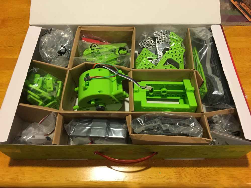
The first step in prototyping the “hardware” was construction. I built the Meccasaur to the factory specs using the included instructions. They were pretty good and it was rewarding to go from a box of parts to a giant dinosaur.
 This will soon be a dinosaur
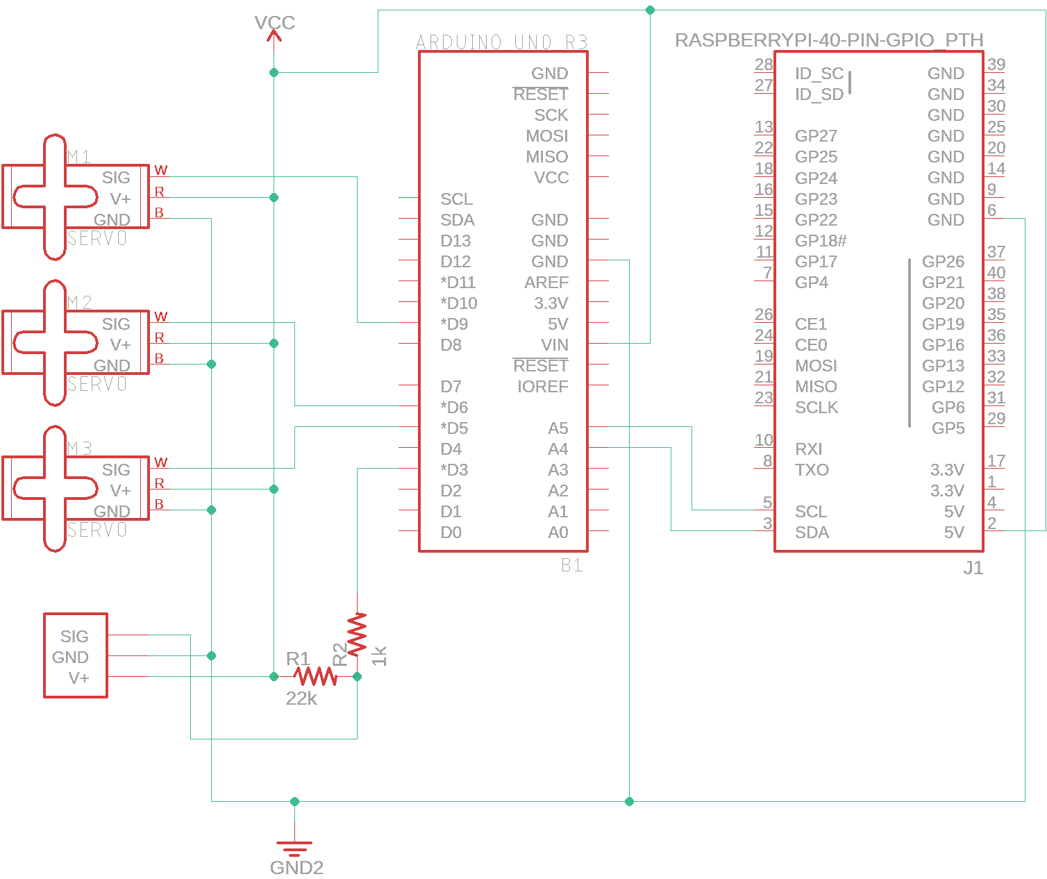
I designed a schematic for this project using EAGLE. This illustrates how the Pi and the Arduino connect to one another and to the three servos (one for the mouth, and one for each arm). The small rectangular component on the bottom left is the LED and embedded controller for the Meccasaur’s eyes; more on that later.
 Project schematic
I wanted to get spun up on the Arduino programming before the new parts I had ordered arrived so I started the project with a full sized Arduino Uno (actually a knockoff made by OSEPP) that I already had laying around. Since I didn’t have any of the servos yet, I investigated what I could do with the existing Meccano hardware…
All Meccano peripherals use a serial protocol called MeccaBrain. The Meccasaur isn’t officially branded as a MeccaBrain-compatible product, but I figured that since they offer a three wire multicolor LED as part of MeccaBrain and the LED that came with the Meccasaur is a three-wire multicolor LED that it was probably the same thing, or at least compatible. Meccano nicely provides documentation and an Arduino library to assist with interfacing with their products. I implemented this to talk to the LED, but from my testing it seemed unreliable at best. I had to send the MeccaBrain messages multiple times in order to get the LED to change colors, and even then sometimes it wouldn’t change. With that experience in hand, I decided to not bother with the Meccasaur servos.
Servo motors are pretty cool. They’re a combination of a motor and a sensor that measures the motor’s position. This allows for it to accurately rotate to a specified angle. By attaching things to the motor, you can make real-world objects respond directly to coded instructions. They’re also inexpensive, so are a great way to get started with a project like this one. Most servos use a three-wire configuration for power, ground, and data. Using the Servo library provided by Arduino, they’re very easy to interface with.
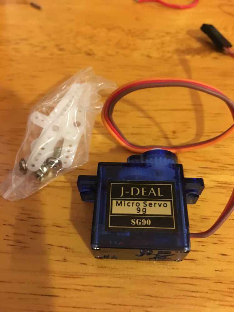 J-Deal Micro Servo
Once the J-Deal servos arrived I had to modify the Meccasaur to find a way to attach them. For the arms it was pretty easy, I removed them and just attached them by screwing them directly to the arm of the servo. For the mouth, I had to get a little more creative. I initially tried mounting the servo on the side of the jaw, to drive it directly, but couldn’t get it to work. I then realized that the mouth naturally falls to an open position due to gravity. I ran some fishing line to the bottom jaw and attached it to a servo mounted behind the head. The servo lifts the jaw by pulling on the fishing line. It worked great and turned out to be a more aesthetically pleasing location for the servo to go anyway.
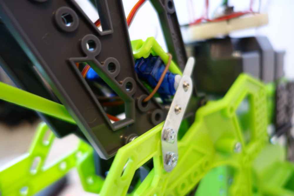 Arm mounted directly on servo
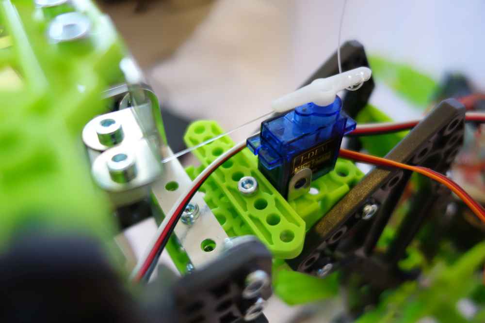 Servo connected to mouth with fishing line
I ordered a Raspberry Pi Zero W without pins attached. I determined that if I attached a minimal amount of pins to the Pi I could make it fit on the same small breadboard as the Mini Arduino. Time to break out the soldering iron!
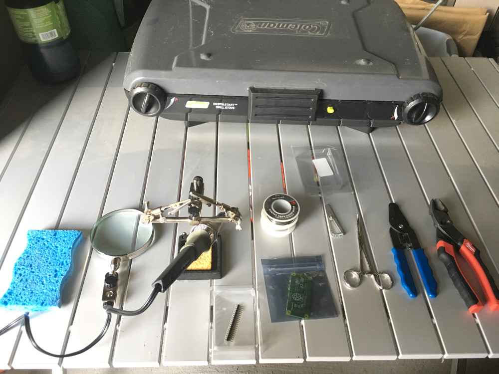 My outdoor soldering station
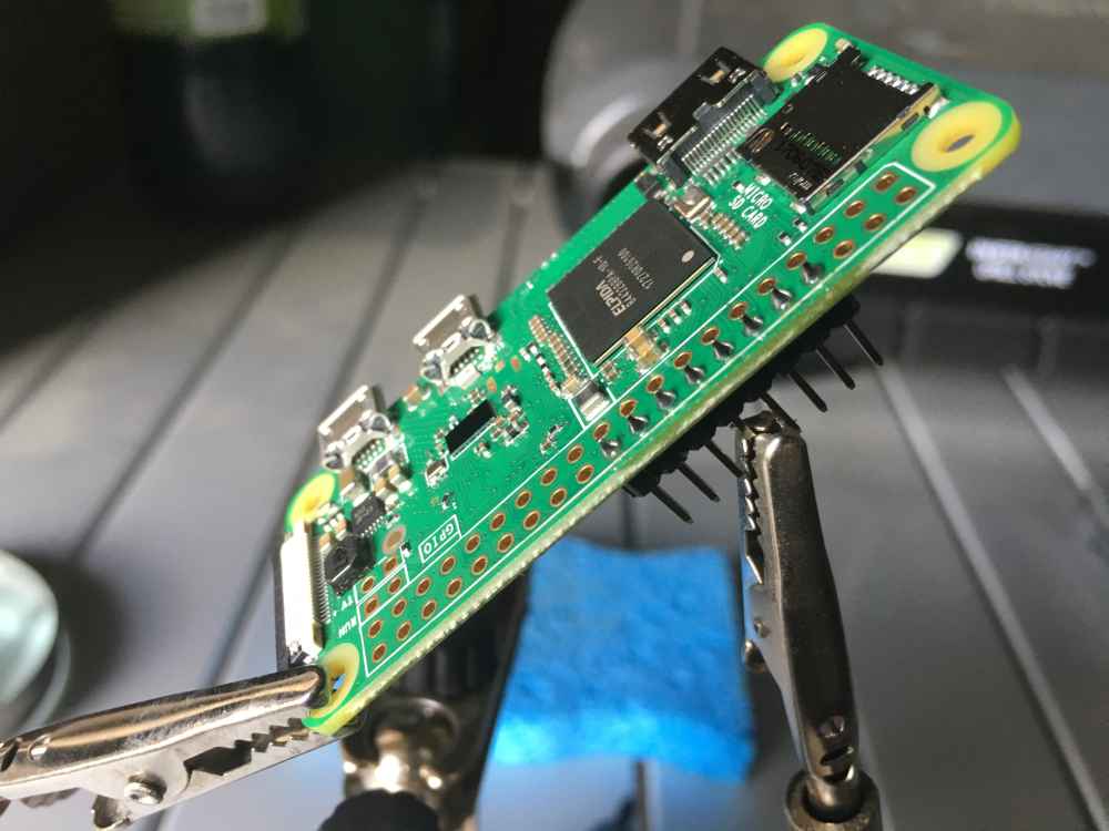 First set of pins attached
 All pins soldered
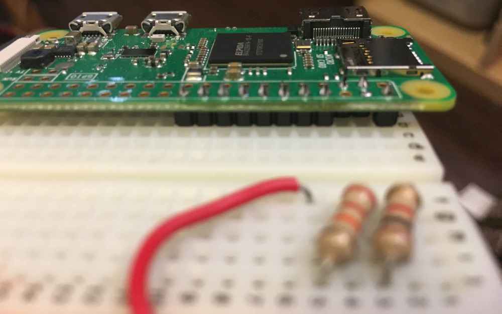 Rasberry Pi attached to breadboard
After attaching the pins to the Raspberry Pi and attaching it to the breadboard I flashed it with Raspbian and made sure it booted.
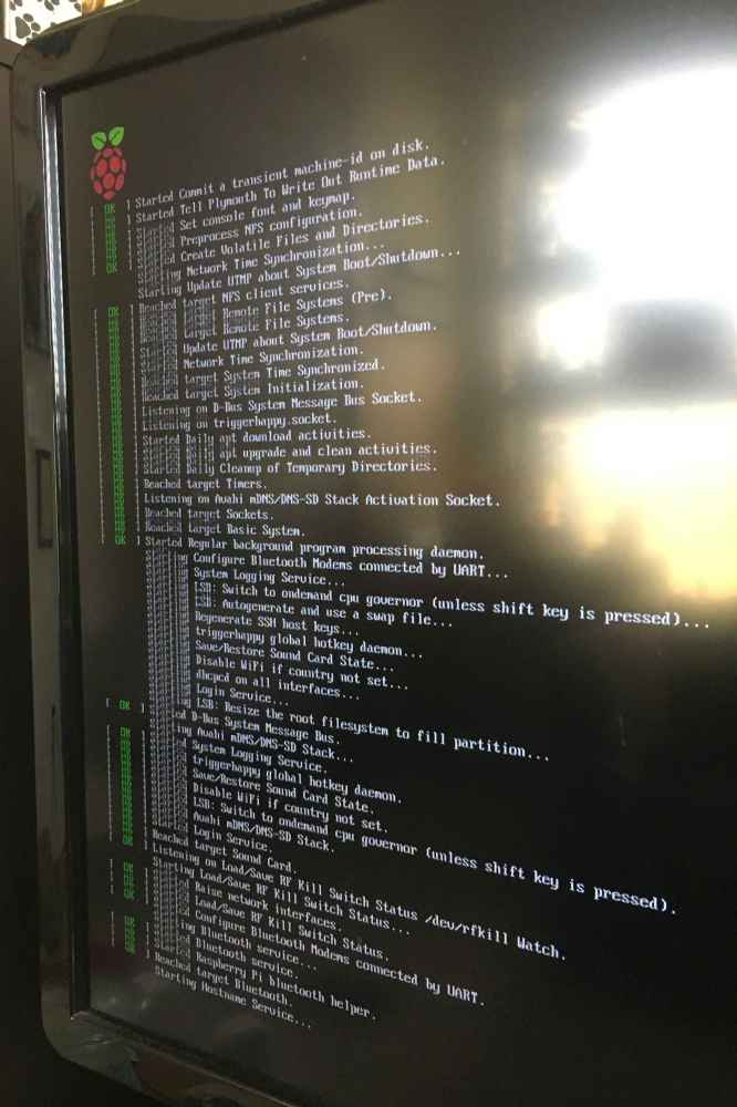 Boot up success!
The final hardware step was to put it all together. I attached the Arduino to the breadboard along with the Pi and wired it up.
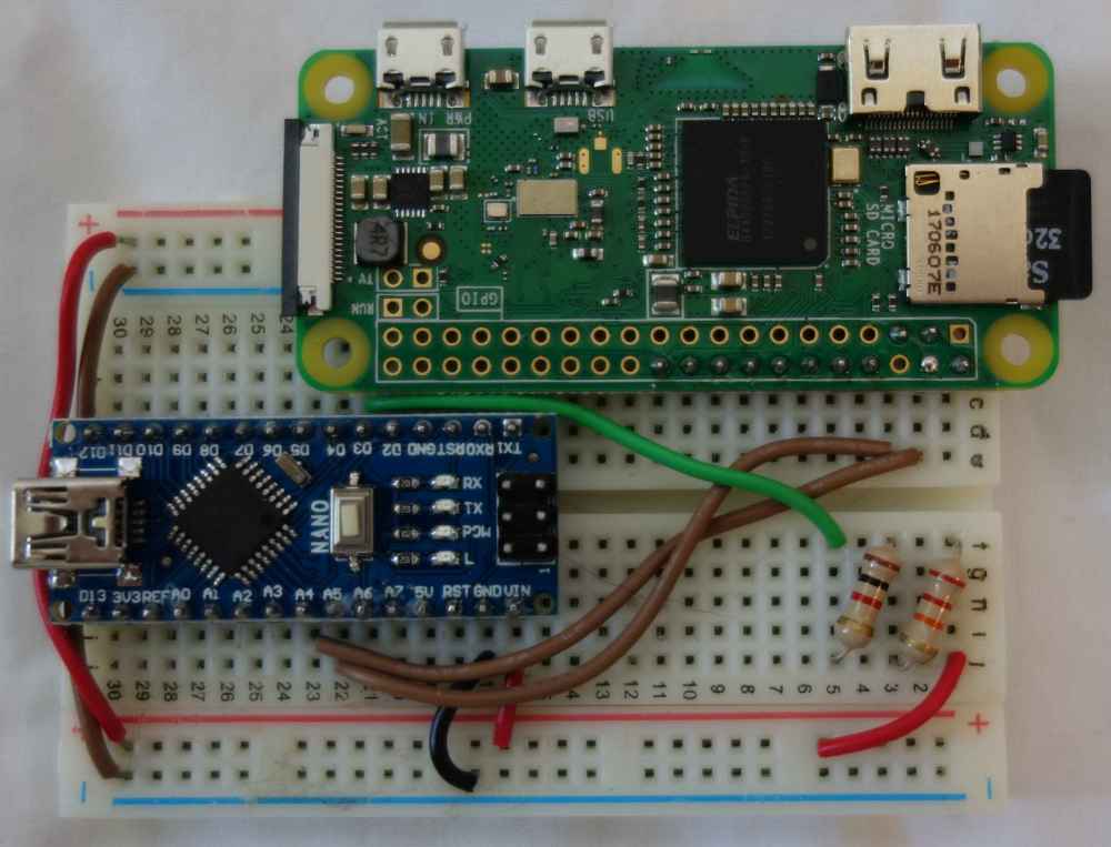 Hardware connected; red and black wires are power and ground and brown in the middle are I2C
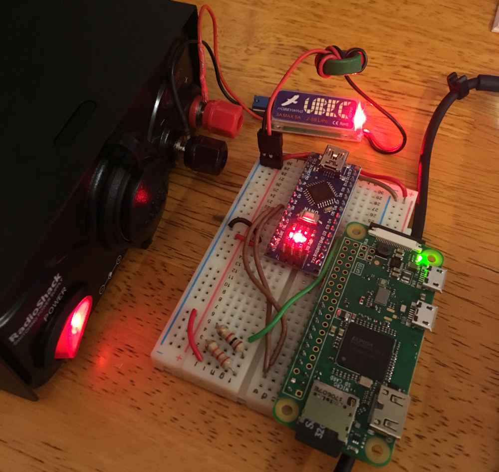 Plugged in and powered up
With the hardware configured, it was time to write the software for both boards.
Software Design
I developed three programs to control the animatronic. action_recorder, control, and actuator.
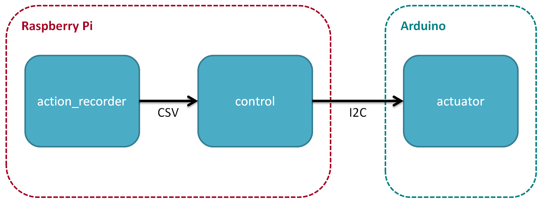 Software architecture
action_recorder is a Python program that runs on the Raspberry Pi. It provides the user the ability to easily generate timing cues for the animatronic. I initially didn’t plan on writing this program, just recording the cues manually. After attempting to synchronize some mouth movements manually with the audio track, I realized it would be much more efficient to write something that would allow for easily recording a “rough cut” of the motion which I could then fine tune later. The program is pretty simple: the user executes it at the same time as starting the audio track. As the audio plays, the user presses the space bar to annotate when the mouth should open. The specified cues are then timestamped and recorded to a CSV file which the control program can interpret. These cues aren’t perfect, but it’s a lot easier to fine tune them than generating them manually.
control is a Python program that also runs on the Raspberry Pi. It acts as the primary show control program for the animatronic. Cues are loaded from a CSV file into memory and then continually checked against a timer. Once the appropriate time for any given cue occurs, it is translated into a message that is transmitted over I2C to the actuator program running on the Arduino. I selected I2C as the protocol to connect these devices as it is an industry standard and has good support on both the Python/Raspberry Pi and Arduino sides. The SMBus Python library provides the I2C capability on the Raspberry Pi side.
actuator is a C++ program that runs on the Arduino. It converts the actual cue messages received over I2C from control into the actual electrical signals to drive the servos and LED. The I2C messages each contain three fields: a type field, an ID field, and a setting field. The type field indicates the device category, L for Arduino LED, M for Meccasaur LED, and S for servo. The ID field indicates a specific device number for a type. The setting field is contextually based on the device type and is used to actually configure the device state. For the Arduino LED, this is a simple on/off. For the Meccasaur LED, one of seven colors can be selected. Finally, and most importantly, the servo angle can be selected. This is used to control the arms and mouth. I was able to interface with I2C using the Wire library provided for Arduino and the servos with the Servo library. Servos work using PWM (pulse-width modulation) signals to indicate position. As such, they must be connected to PWM capable pins on the Arduino. I wrote my code to handle up to five servos, each attached to a PWM pin, even though I only ended up using three.
All the code for this project is available on GitHub, here: https://github.com/xtruan/animatronic-control.
Testing
For testing I wanted to do something fun that would also lend itself reasonably well to animation. I was able to find the on-ride audio for Disney’s Journey into Imagination with Figment and figured that was a great candidate. EPCOT is my favorite park at Walt Disney World, and Figment is all about setting your imagination free so I figured he would be a good fit. Plus I could set my dinosaur’s eyes to be yellow, so that was an added bonus!
The below video repeats the same section of animation twice. In the first section, I dubbed the audio over the video as the super cheap servos I used turned out to be… cheap. They weren’t great at maintaining their position under load and as a result tended to vibrate around the position and vibrate LOUDLY. The second section uses a microphone and actually records the audio track to demonstrate the actual synchronization. However the servo noise is loud enough that it competes with the audio playback in that section.
Final Thoughts
I had a great time with this project. I really think the control system I came up with is pretty representative of how a system like this operates in the real world. With that said, there’s definitely a few things that I would change if I were to do it again:
- Buy better servos - The servos I bought were cheap, but they were barely up to the job for moving the arms. The arms were too heavy to be effectively driven by the servos directly. Next time I’d either find a better way to attach them, or use beefier servos.
- Do more experimentation with the Meccasaur drive motor - The Meccasaur came with a drive motor assembly that was powerful enough to move it around with. I should’ve done some more experimentation with it to see what was possible. The lack of documentation and general dumbed-down-ness for the Meccasaur was pretty disappointing, especially since it looks great.