Recently, I’ve been watching the excellent show Mayday (or Air Disasters in the USA). The anatomy of how complex systems break down and fail has always fascinated me, and this show does an awesome job of presenting that information in an engaging fashion.
One of the recurring themes in the show is the fact that it’s common for air traffic controllers to not have an accurate picture of where specific aircraft are in the sky.
Background
Right now (in most of the world at least) aircraft are tracked by radar. There are two types of radar used in air traffic control, primary and secondary. Primary radar is similar to the active sonar you see in submarine movies. Imagine this awesome scene below but with electromagnetic waves instead of sonar pings (and aircraft instead of Soviet torpedoes) and you get the general idea of how primary radar works: the sooner the signal bounces back, the closer the detected object is to the source.
Secondary radar works a little differently. Instead of simply reflecting a signal like with primary radar, the aircraft actually transmits its own signal back using a device called a transponder. There are multiple benefits to this system. The initial radio signal can be transmitted with a lower power since the aircraft has its own transmitter for the return signal. Because the aircraft is transmitting it can also send more information to the ground. The drawback of the system is that the aircraft is no longer a dumb chunk of flying metal; it must have a transponder.
So for those keeping score, the current system in place gives you range and bearing from the primary radar and pressure altitude which is transmitted using “Mode C” of a transponder operating as part of a secondary radar system. One additional thing to note is that these three pieces of information are also only available when the aircraft is in range of a powerful land-based transmitter.
ADS-B, or Automatic Dependent Surveillance - Broadcast, is meant to solve this problem. It works kind of like the transponder in secondary radar, except that it doesn’t need to be interrogated by a ground station, and it provides a lot more information. An aircraft equipped with ADS-B transmits speed, heading, altitude, latitude, and longitude which it gets from the aircraft’s own navigation system (usually using a high fidelity GPS unit) at regular intervals. Coupled with a network of ADS-B ground stations, this technology could eliminate the need for expensive radar facilities. There are also numerous other benefits. Air traffic controllers can have a much clearer picture of the sky, allowing for improvements in safety and efficiency (more accurate aircraft position knowledge allows aircraft to be placed closer to one another allowing for better utilization of air corridors and runways). Other aircraft can receive the signals increasing the pilots situational awareness. Remote airports can automatically turn on the lights when an aircraft gets near. In other words, the sky’s the limit…
Building the Receiver
The other major benefit of ADS-B is that building a ground station can be done on the cheap. Not only that, it can be put to good use by sending the information to the FlightAware aircraft tracking service. In exchange for you feeding them information, they upgrade you to an Enterprise account which they normally charge $89.95 per MONTH for. Talk about a sweet deal since the cost of building a receiver is only a little more than that!
I decided I wanted to build my receiver in a waterproof enclosure so I could mount it outside. I also chose to use Power over Ethernet so I only had to run a single cable to my receiver.
Parts List
- Raspberry Pi 2 Model B Project Board - Amazon ~$40
- Case for Raspberry Pi 2 Model B - Amazon ~$9
- NooElec NESDR Mini 2 SDR - Amazon ~$23
- ADS-B 1090MHz Band-pass SMA Filter - Amazon ~$20
- 1090MHz ADS-B Antenna - Amazon ~$45
- Hobbywing 5V/6V 3A Switch-mode UBEC - Amazon ~$8
- Power over Ethernet (PoE) injector - I actually had one of these laying around, I linked a similar looking one on Amazon ~$12
- SMA male to MCX male RF coax cable - Amazon ~$6
- Type N male to SMA female RF coax cable - Amazon ~$8
- Watertight box - Walmart ~$7
- Weatherproof cord connector - Amazon ~$18 for 10
- A few Ethernet cables of various lengths - I had these. A great place to get cables of all types for cheap is Monoprice.
- A USB extension cable - You may not need this, I needed it so I could fit everything in the watertight box.
- A microSD card that's at least 8 GB - I used a 32 GB one because I had it already. Make sure you have a way to connect this to a computer.
- An RJ45 keystone jack - You probably won't need this if you have an RJ45 crimping tool. I had one and thought it would be easier to use it to make the PoE splitter, now having done it I'm not so sure.
- Velcro tape - I had this too, very useful for getting things to stay in place.
- Soldering kit - This is only required for connecting a few wires. You could probably get away with using those twisty things from Home Depot if you're uncomfortable soldering.
Putting It All Together
First, some pictures of the goods. From top to bottom on the cardboard are the NooElec radio, the Raspberry Pi, the ADS-B filter, the Hobbywing UBEC, and the PoE injector. On the right is the ADS-B antenna.
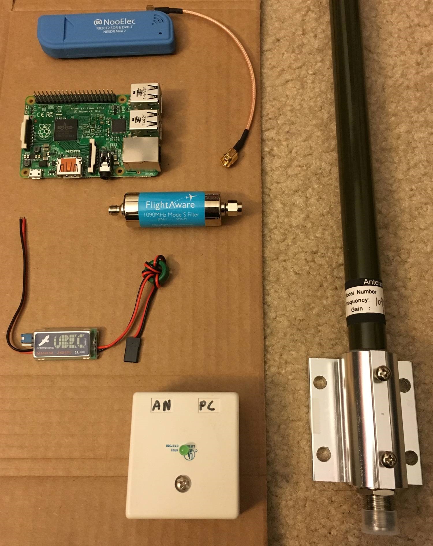 Most of the major components
The brain of this project is a brand new Raspberry Pi 2 Model B board. I actually had an old “vintage” Raspberry Pi 1 Model B laying around so I decided to take a comparison shot. The new one has twice as many USB slots, and has ditched the composite video connector. Not to mention that it’s 6x faster.
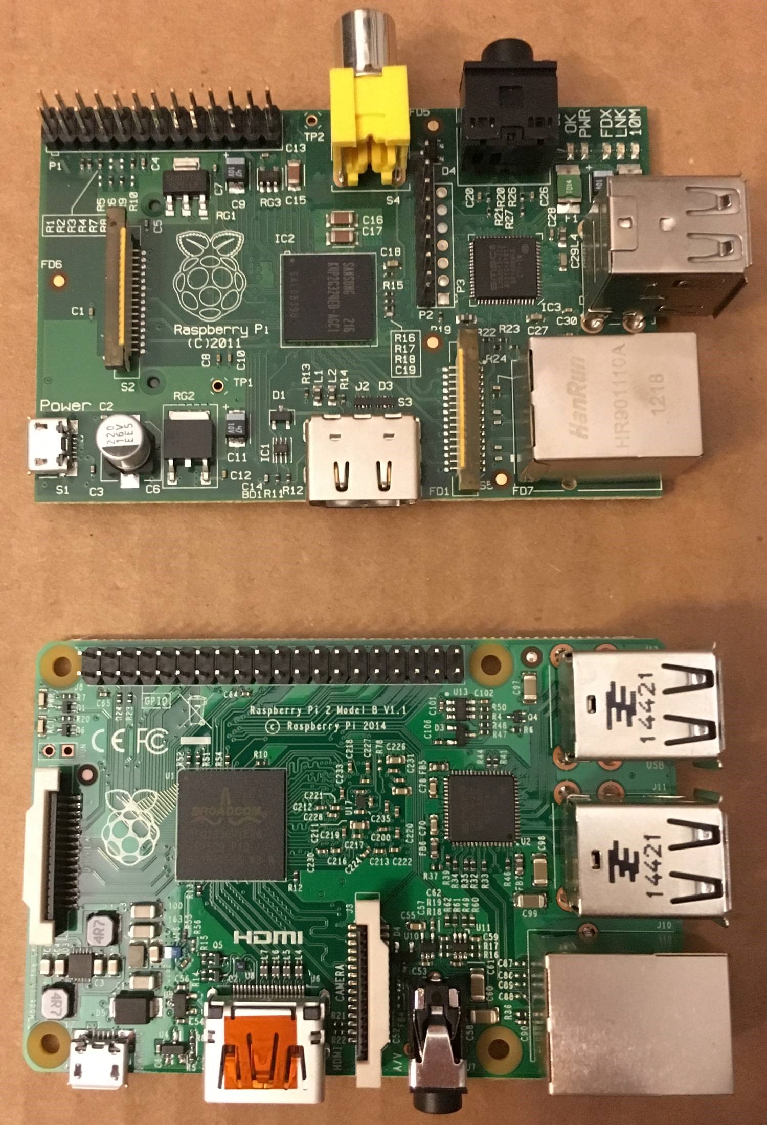 Old (top) and new (bottom)
The first thing I did was flash the PiAware system image to the microSD card. On Windows, you need to download the PiAware on Raspbian Linux 2.1-3 ZIP file, as well as the Win32DiskImager utility ZIP file.
Plug in your microSD card, and extract the IMG file from the PiAware SD Card ZIP. Then, open up Win32DiskImager. Browse to the location of the IMG file and select it, then select the drive letter of your microSD card. Click write and Win32DiskImager will do the rest.
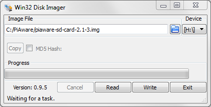 Preparing to write
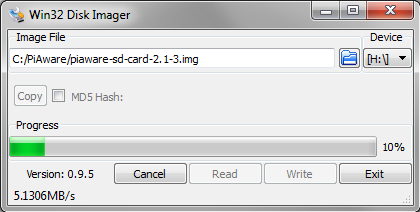 Writing image
Most of the hardware part of this project is “plug and play”. The most time consuming part is assembling the PoE components. Ethernet cables have a few unused wires when they’re being used in 10/100 mode, and we can deliver power for the Raspberry Pi over them. A PoE injector takes energy from a wall socket and transfers it onto these unused lines in its output socket, while also passing through data coming in through its input socket. On the other end of the cable, the UBEC takes this voltage and efficiently steps it down to the 5V required to power the Raspberry Pi. UBECs are actually intended to be hooked up to a battery, the idea being that as the battery discharges and the voltage drops, constant power is still being fed to whatever the battery is powering. In fact, the UBEC is basically just a glorified switching regulator. I thought about using a cheap linear regulator instead, but decided to spring for the UBEC because it’s a lot more efficient, especially for a device that’s going to be operating 24/7.
Lets talk about which wires in your Ethernet cable are doing what. There are eight wires in an Ethernet cable. They are green, green/white, orange, orange/white, blue, blue/white, brown, and brown/white. In 10/100 mode only the green, green/white, orange, and orange/white are used for data. This leaves the others free to carry power. We’ll be tying the blue and blue/white wires together to +DC and the brown and brown/white to -DC.
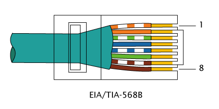 Ethernet cable pinout
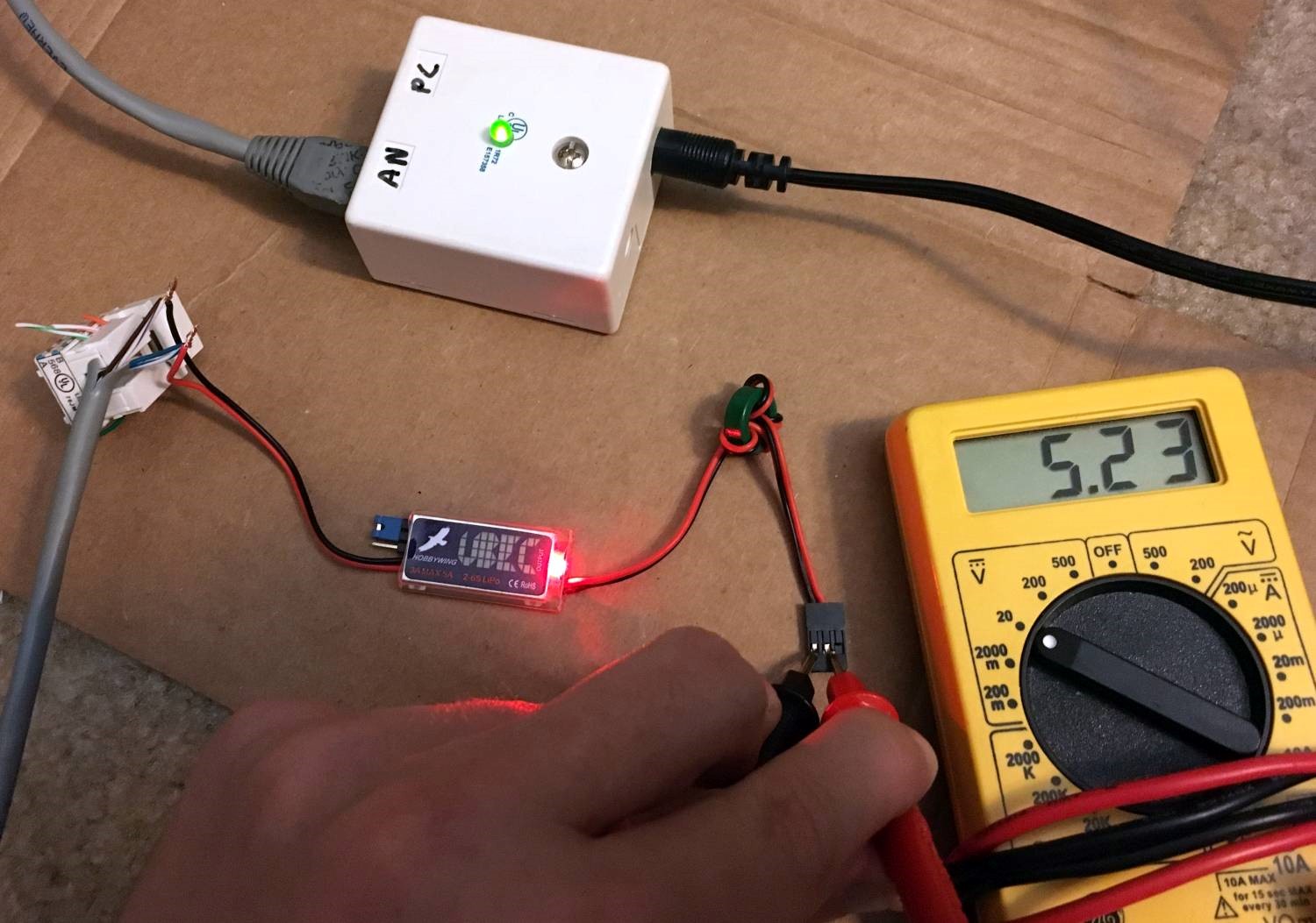
I wasn’t sure what voltage my PoE injector was putting out, so I hooked it up to an Ethernet cable and measured the voltage between pin 5 and 7 with a multimeter. It came out to about 15V which is perfect since the UBEC we have works over a range of 5.5V to 26V. The one I linked in the parts list should supply 12V.
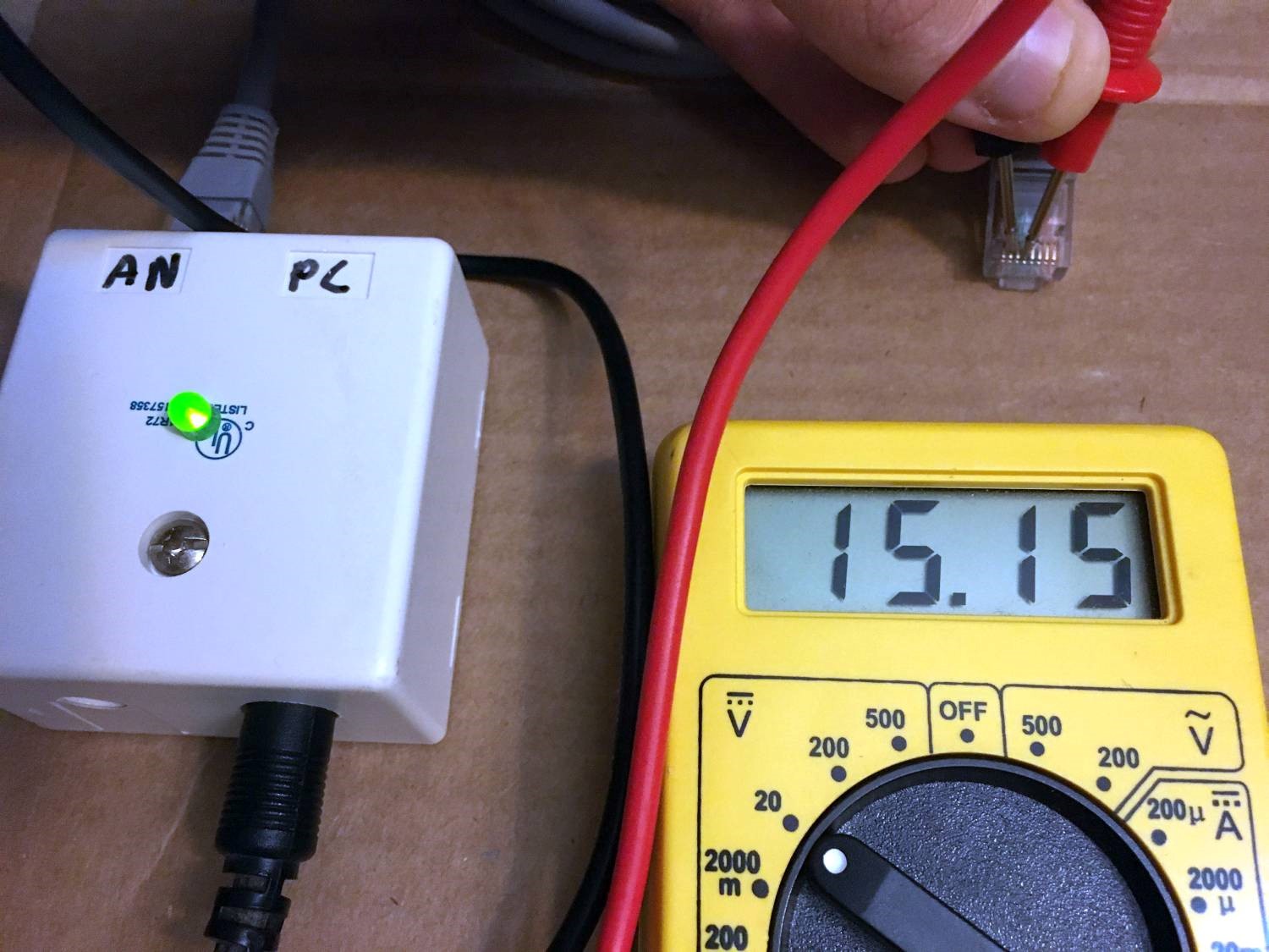 Testing the PoE injector
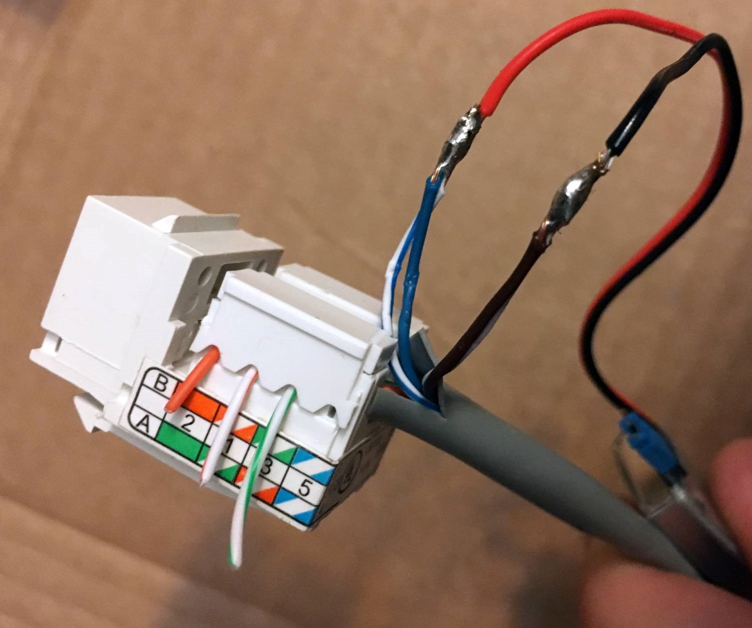
After this test, I wired up my RJ45 keystone jack to an Ethernet cable with one end cut off. Two things to note: First, make sure this cable is long enough to reach from the PoE injector to the Raspberry Pi. You don’t want it to be too short! Second, slip a weatherproof connector over the Ethernet cable with the metal piece of the connector facing the cut off end of the cable. An RJ45 connector is just barely too big to fit through the weatherproof connector, so if you forget to do this you’ll have to cut the cable and rewire one of the ends. I speak from experience. The RJ45 keystone jacks are great because they don’t require any tools to wire up, you just line up your wires with the correct slots and press down on the plastic shields. The jack contacts slice through the insulation so the wires don’t even have to be stripped. I split out the blue, blue/white, brown, and brown/white wires and wired the rest into the jack. Since I have an RJ45 crimp tool if I were to do this again I think I would’ve foregone the keystone jack and just crimped a connector onto the green, green/white, orange and orange/white wires.
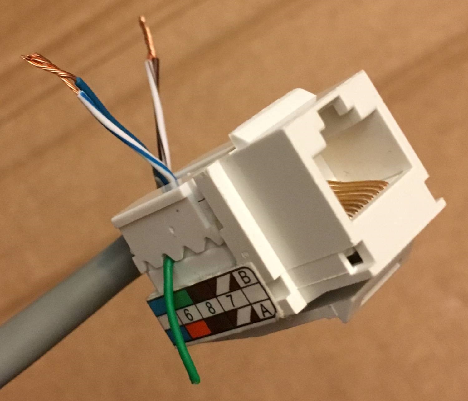 Left side wired up
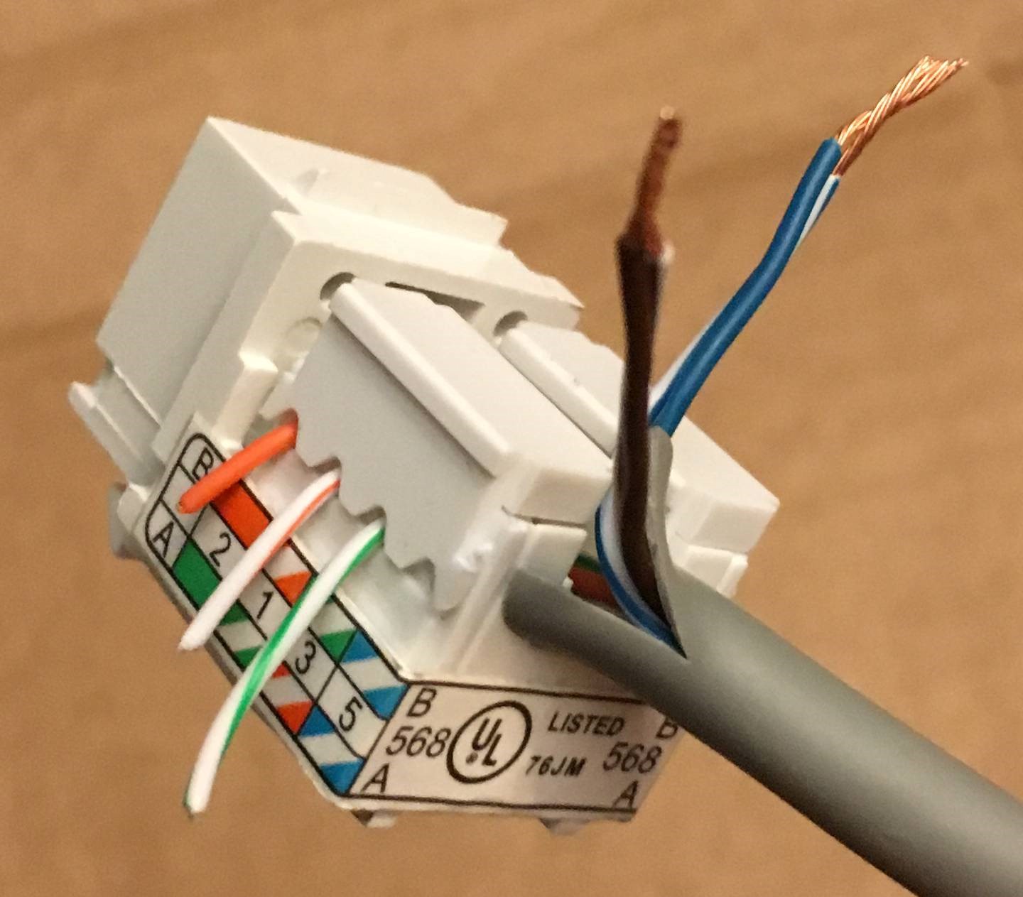 Right side wired up
The next step is to hook up and test the UBEC. Connect the red wire to blue and blue/white and the black wire to brown and brown/white. Note that there’s a jumper on the UBEC for selecting 5V or 6V output. Mine came set to 5V, but it’s worth checking that it’s there on yours as well. I turned on the power and measured the output. Right around 5V!
 Testing the UBEC
Now that the power system is ready, it’s time to clean it up. I recommend soldering the wires together to get a clean connection, but you can also use screw on wire connectors. Soldering is really a valuable skill and isn’t that hard once you have a little bit of practice. Of course it helps to have a dedicated soldering work station with a lighted magnifier, a high quality iron, and a professional ventilation system… but failing that you can do what I did. Cover a baking sheet in aluminum foil and do all your soldering on the stove. Turn on the stove hood to suck away any nasty fumes.
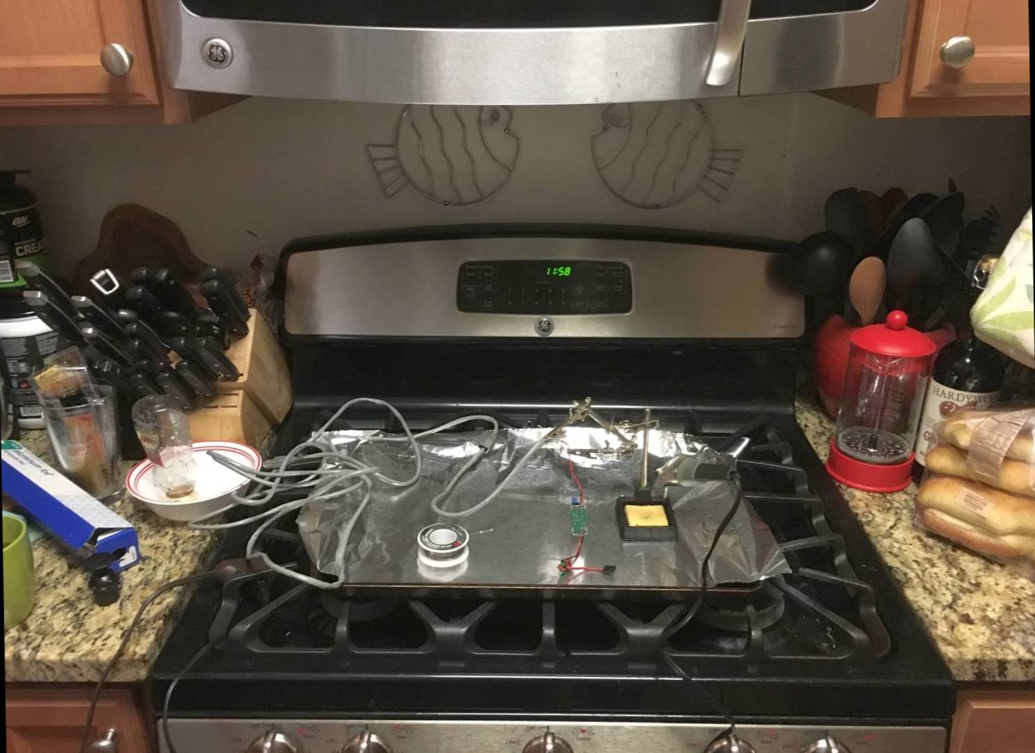 Professional soldering workstation
I clamped the wires together on a soldering stand and went to town. I think it turned out pretty good!
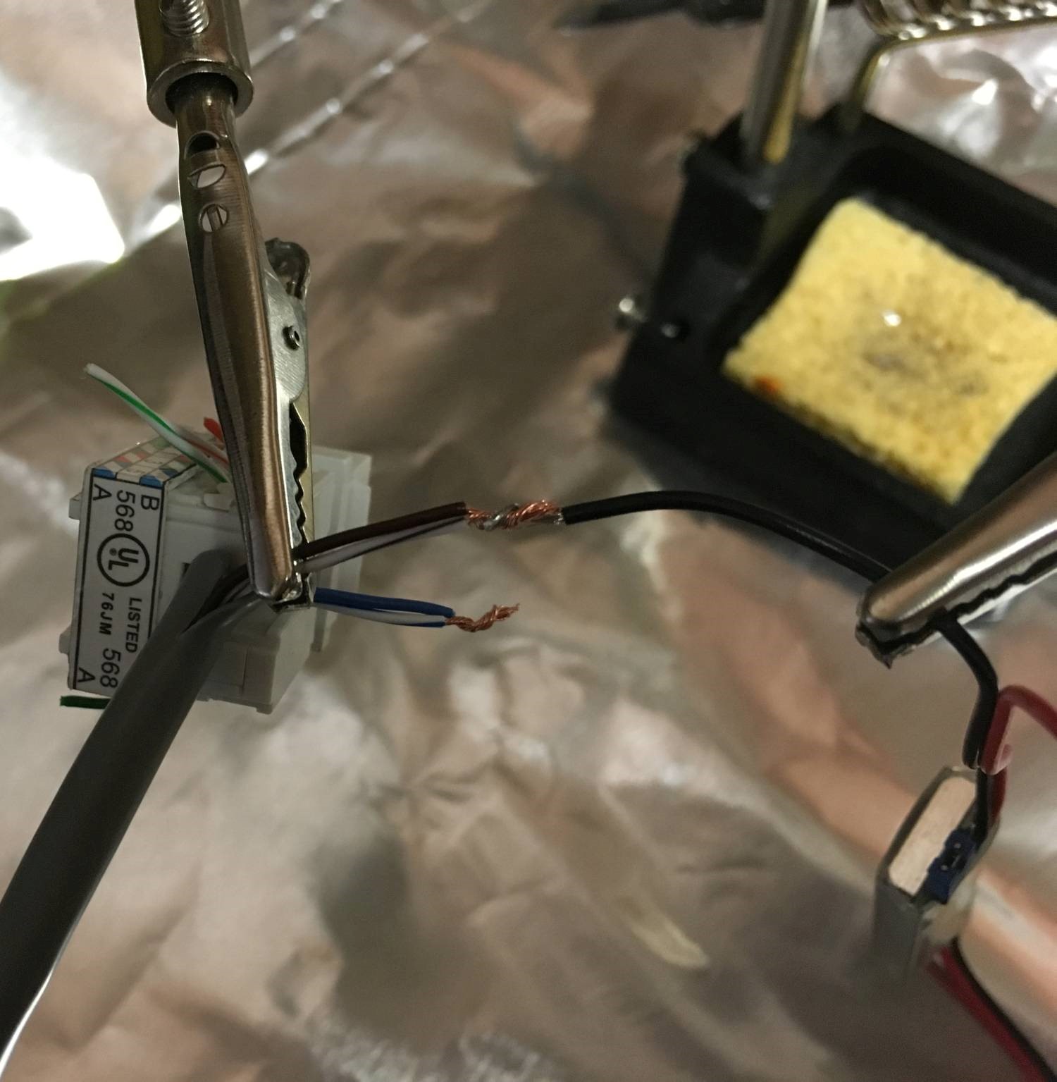 Clamping the wires in place
 Soldering complete
After the soldering job was done I wrapped up the UBEC and the RJ45 keystone jack in electrical tape and stuck a piece of Velcro on so I could attach it somewhere later.
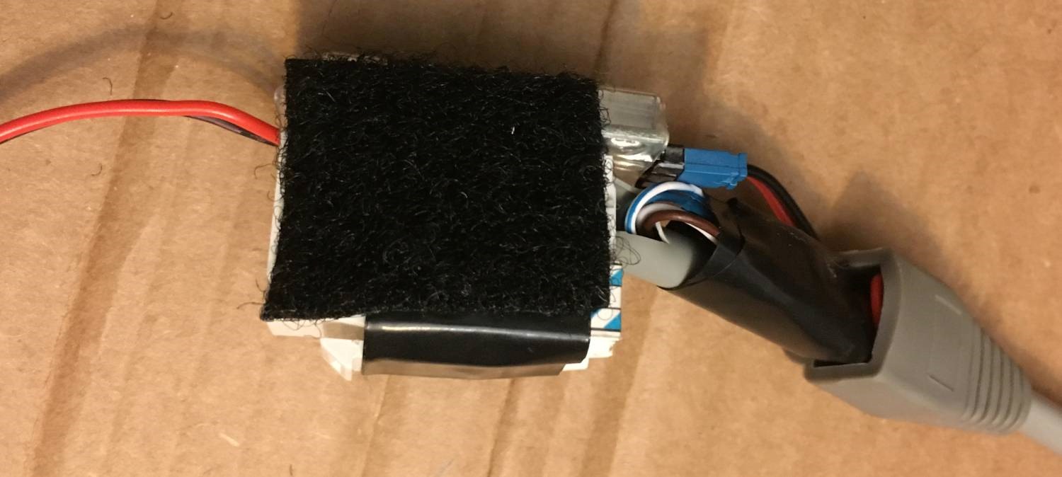 All wrapped up and Velcro stuck on
Now that the hardest part is over, it’s time to go back to the Raspberry Pi. Unplug the microSD card from your computer (it should be imaged by now) and plug it in to the Raspberry Pi. Then put the Raspberry Pi into the case. Now it’s time for the next test. Plug the output connector on the UBEC into the Raspberry Pi’s GPIO connector so it covers pins 2, 4, and 6 (P.S. there’s a great Raspberry Pi pinout reference here). Turn it on and after a few seconds some lights should come on!
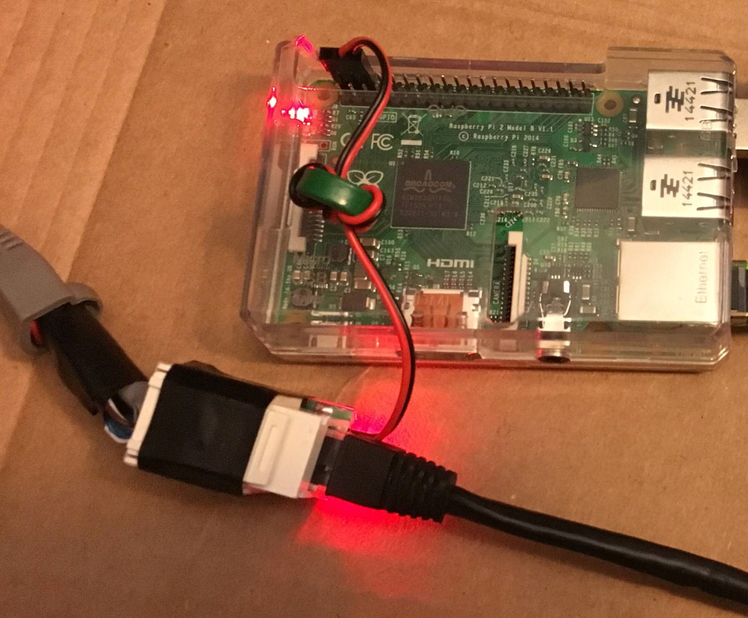 Raspberry Pi test
Everything is ready to go at this stage so now it’s a case of packaging it up. I used this legit little box I got at Walmart. I actually bought an extra one because I can think of a million uses for it. Although I was disappointed to learn it didn’t come with the pictured $10… :(
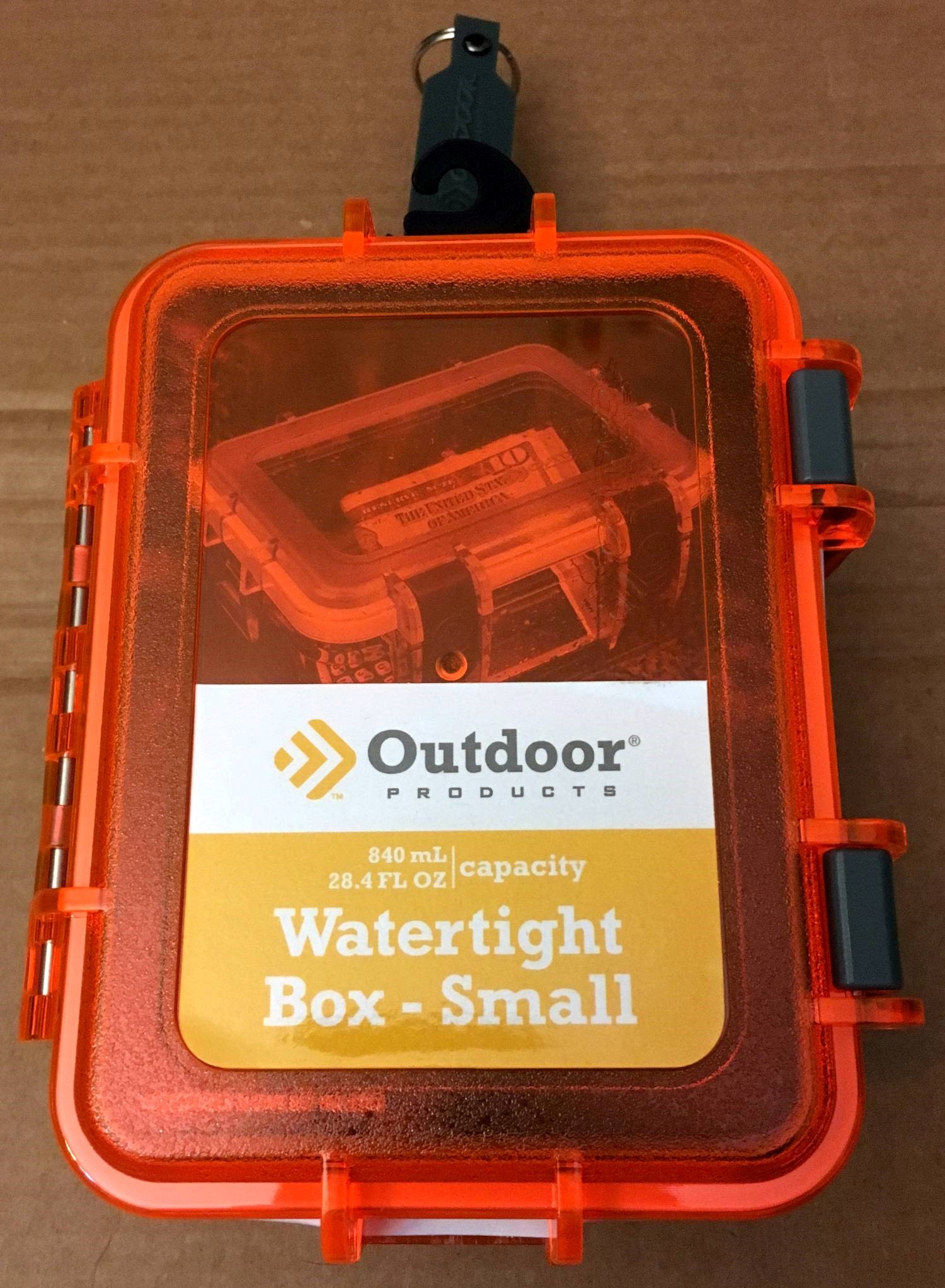 Box closed
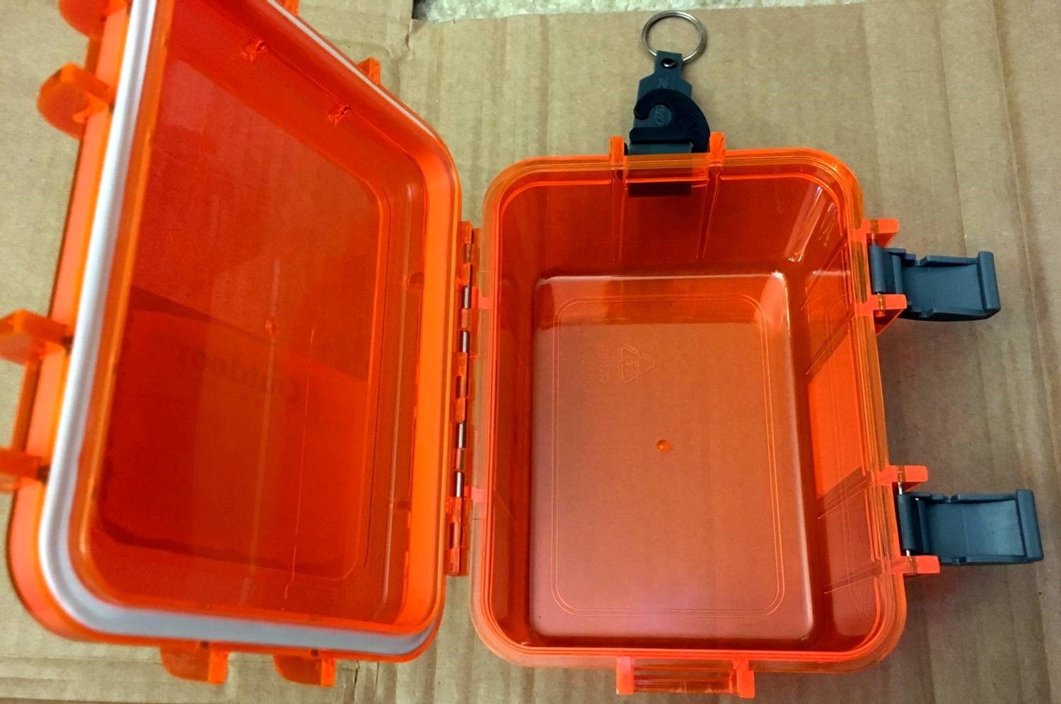 Box opened
I also can’t say enough good things about Velcro tape. I have a roll that consists of two lengths of tape, one has hooks and the other has loops. The back of both tapes have a super-strong 3M adhesive on them. This stuff is awesome for holding all the parts together, but is also easy to remove if you need to adjust anything.
 Raspberry Pi with Velcro attached
It was a tight fit to get everything in. Too tight in fact. When the NooElec radio is plugged into a USB port on the Raspberry Pi, it’s too long to fit in the box. Argh! I solved this with a USB extension cable that’s way too long. I had to roll it up and use it to put the radio on top of the Raspberry Pi. I’d recommend getting a really short extension cable (or a bigger box). I know I used to have a USB wireless adapter that came with a USB extension cable that was about four inches long, but I couldn’t find it unfortunately.
 Everything packed in
I’d recommending experimenting with getting everything to fit before drilling the hole for the weatherproof connector. Then drill the hole with the box empty so you don’t destroy any of the components. I only used one of the connectors for both the Ethernet cable and the antenna coax cable. I’d recommend giving them each their own connector since they come in a ten pack. I also sealed up the connector to waterproof it more. I used hot glue which probably isn’t ideal but should work “good enough”.
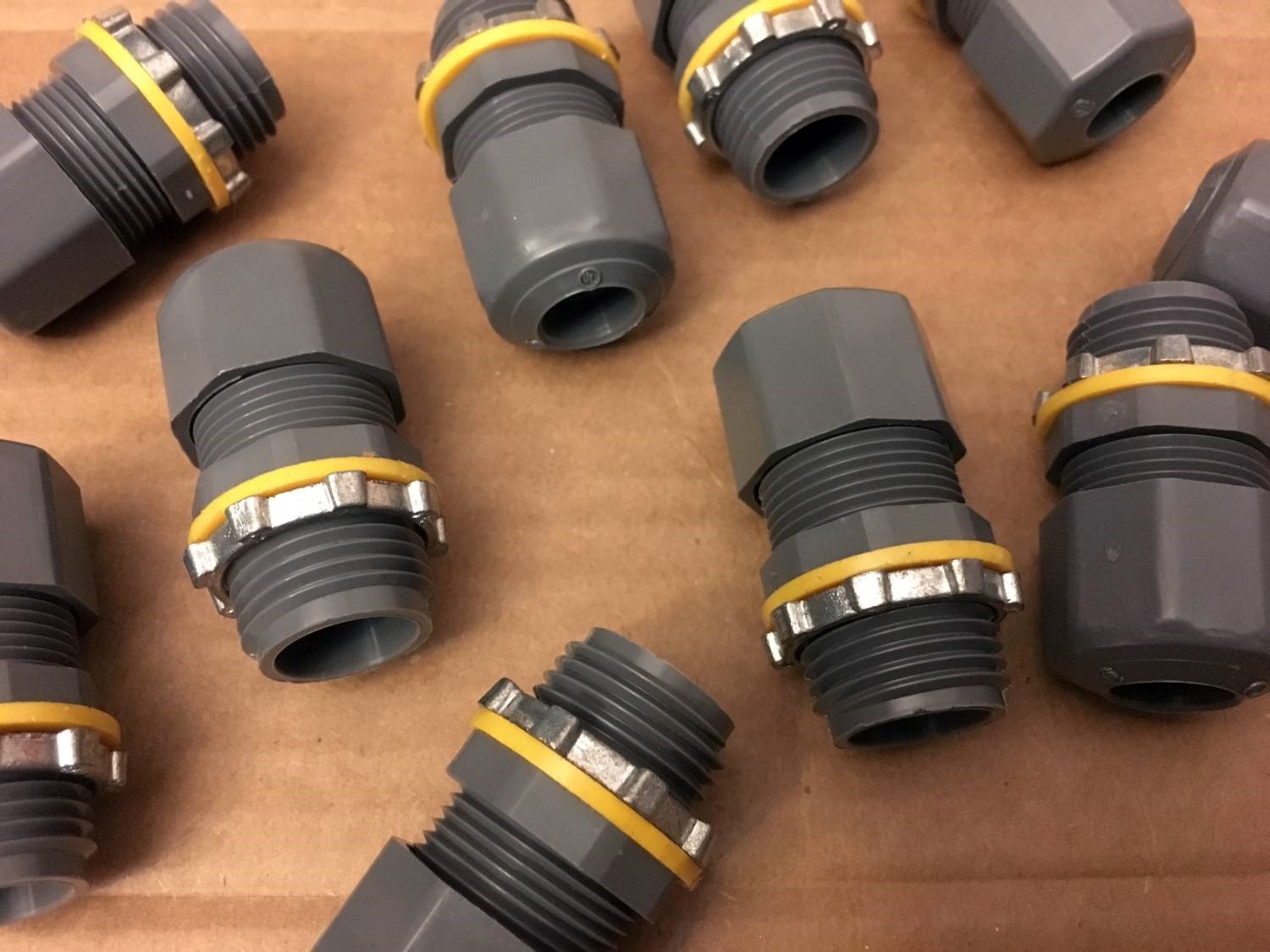 Lots of connectors!
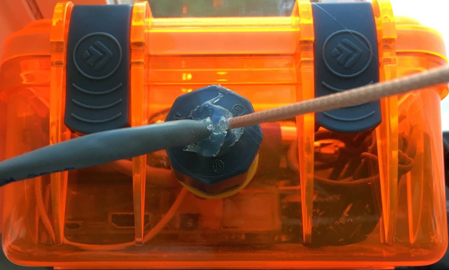 Sealed up
Here are a few more pictures of everything in the box.
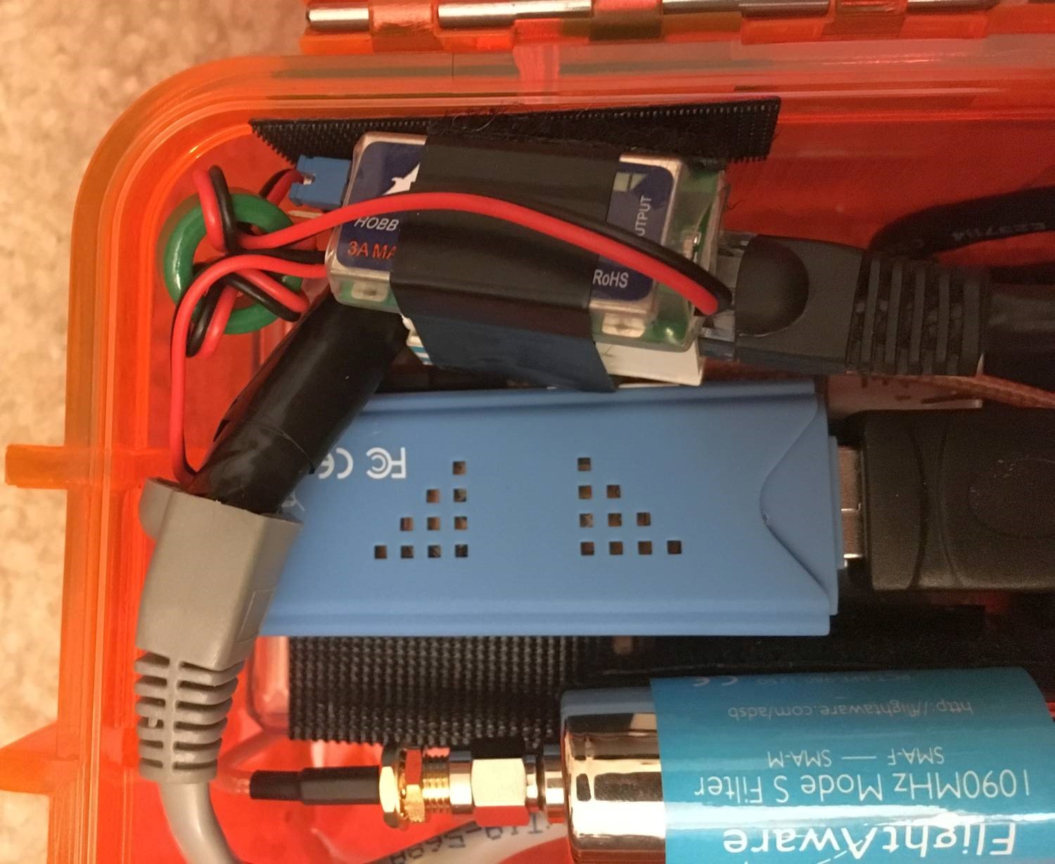 Left side close-up
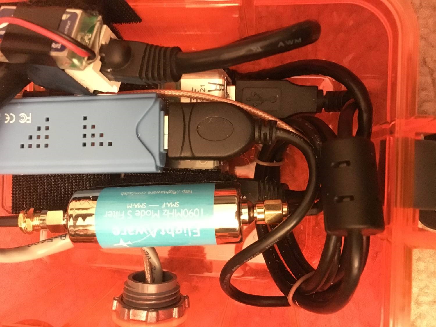 Right side close-up
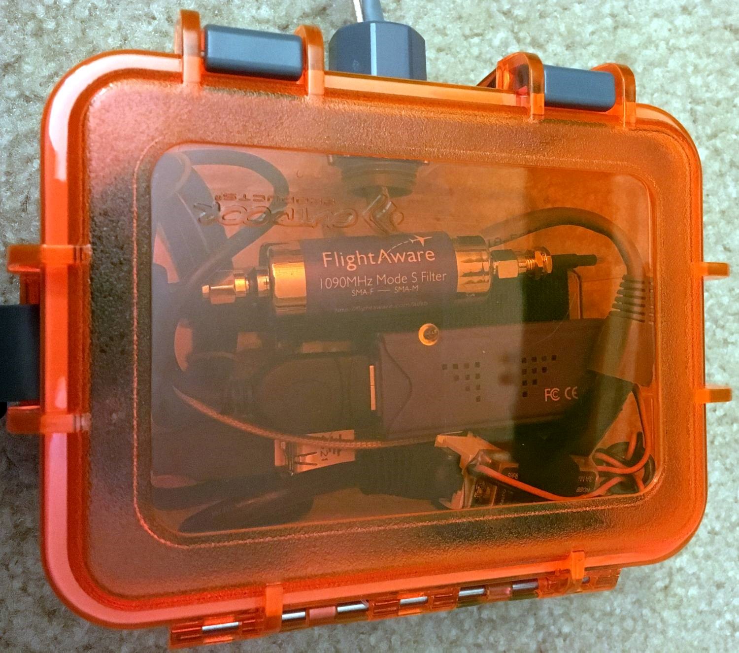 Closed box close-up
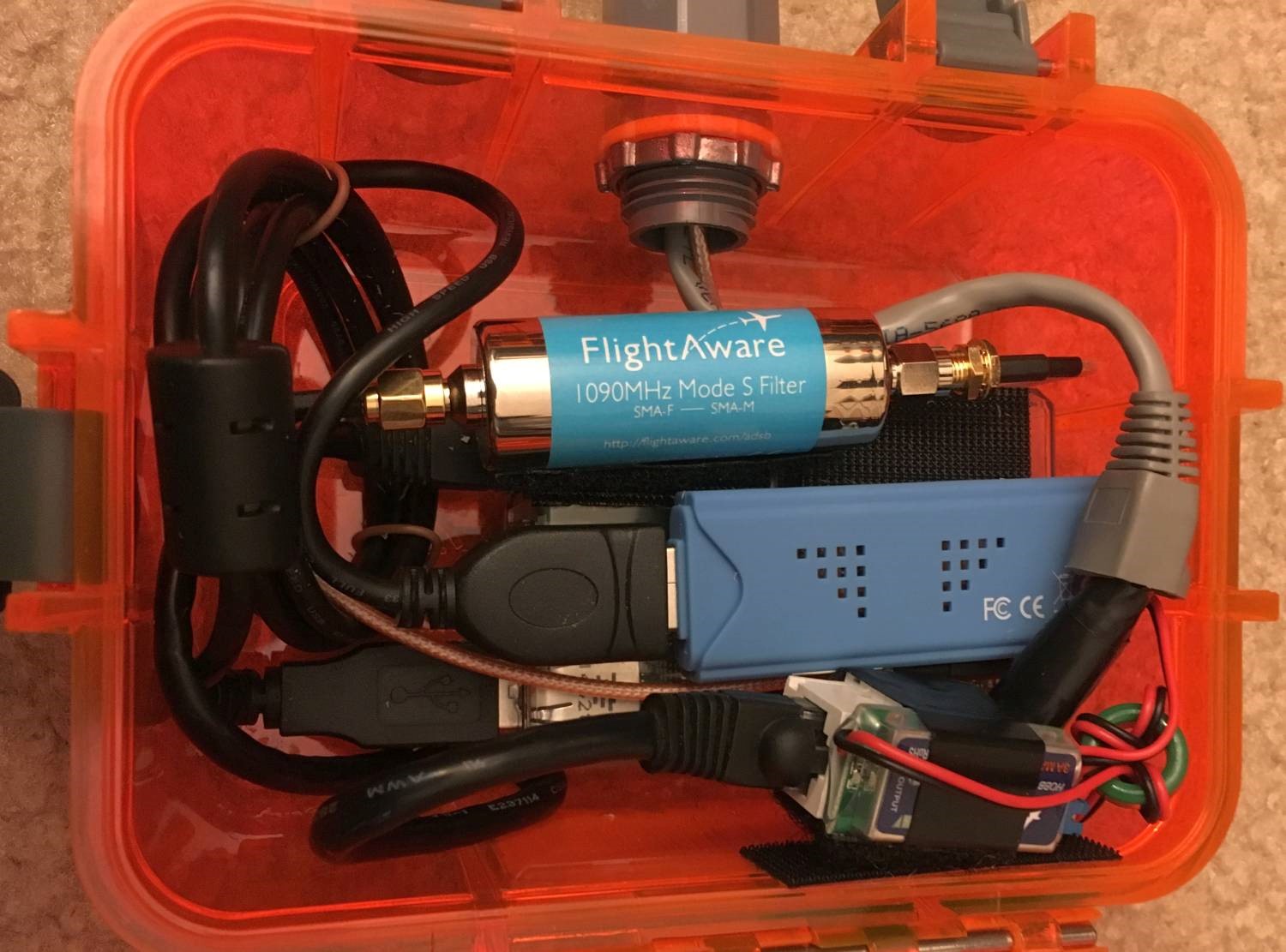 Open box close-up
The ideal place to mount the receiver is somewhere with a 360 degree view of the sky and as high as you can get. The roof of a structure is about as good as you can get. My receiver is mounted on a window on the top floor of my apartment building which is four floors. Not ideal, but I’m getting pretty good returns nonetheless.
Once you have the receiver mounted to your liking, run a cable from the input of the PoE injector to your router and turn it on. Now log into your router and look for it under the list of clients. It should show up as “piaware”.
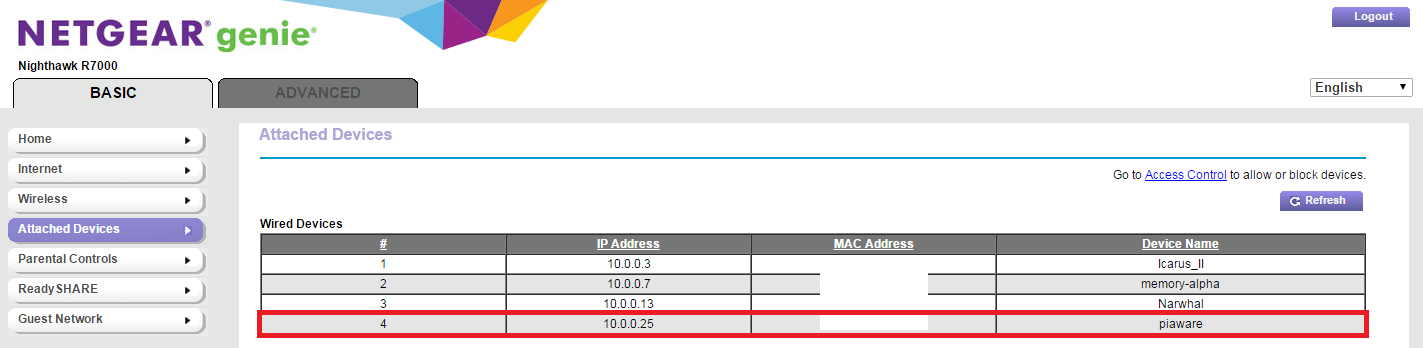 Router client list
By default, the username and password are not in a secure configuration. You should log in and change them via SSH. On Windows, the easiest way to SSH is by using PuTTY. I’m using Cygwin which is a little more effort to set up, but is a lot more powerful. After installing your client of choice, sign in to PiAware running on the the Raspberry Pi using the IP address from the router client list, the username pi, and the password flightaware. Once you are logged in (you will see pi@piaware ~ $ at the beginning of the line) type passwd and press enter. PiAware will now prompt for a new password. Note: when typing the password, nothing will show up. This is a security feature in case someone is standing behind you. Once you enter the new password twice and get no errors it’s changed, you can close the window.
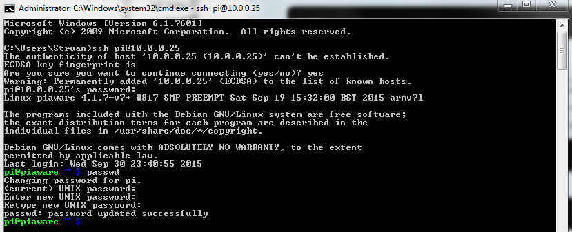 Setting the password
Now, who’s ready to see some planes? Open a web browser and type in the IP address from before, followed by :8080. My PiAware IP was 10.0.0.25 so I typed 10.0.0.25:8080. Assuming everything worked, you should see any nearby aircraft transmitting ADS-B! In my case, this was just a few, they’re highlighted in green.
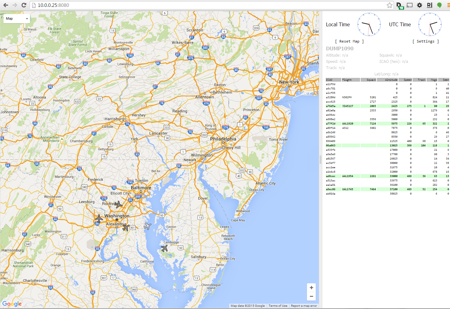 ADS-B transmitting aircraft
There’s a way to see a lot more aircraft. First, claim your receiver with FlightAware to get the benefits of the Enterprise account. After you have claimed your receiver, you should configure its exact location in your profile. I did this by holding my phone running a navigation app next to the receiver and writing down the GPS latitude, longitude, and altitude. Once you’ve set this up (don’t worry, FlightAware will not show your exact location on a map) you should start receiving multilateration (MLAT) reports, they’re highlighted in blue.
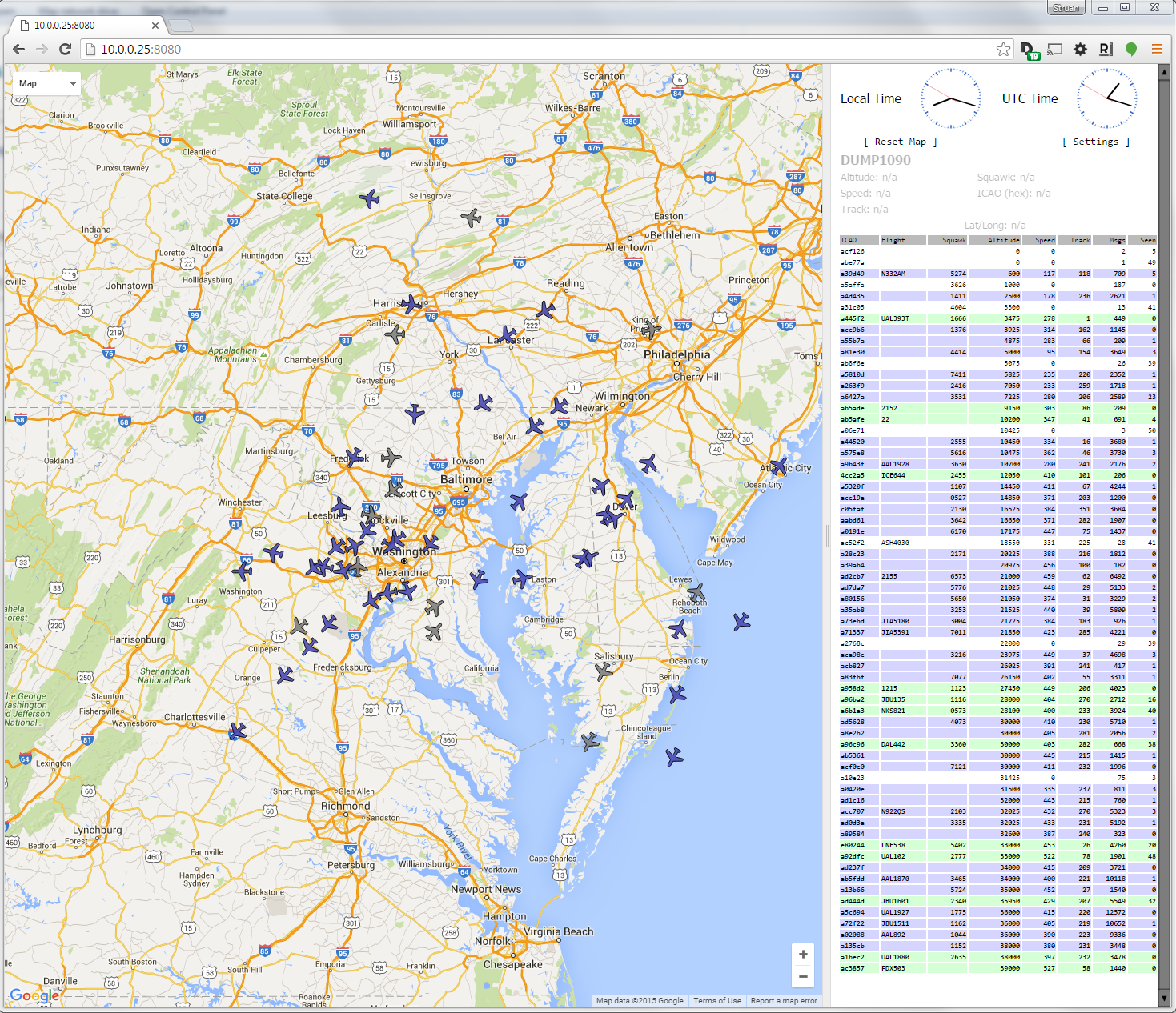 ADS-B and MLAT
Multilateration works by using the existing secondary radar system. Remember above we talked about how transponders work? When a transponder replies to interrogation, if there are enough receivers nearby, the exact time the signal reaches each receiver can be recorded and this information calculated into position data. Since our ADS-B receiver works on the same frequency that transponders reply on (1090 MHz), and FlightAware knows our exact position, we can participate in multilateration. Cool, right?
Resources and References
This is a list of sites I found useful while doing this project and writing the post.
- https://flightaware.com/adsb/piaware/build
- https://en.wikipedia.org/wiki/Automatic_dependent_surveillance_–_broadcast
- https://en.wikipedia.org/wiki/Secondary_surveillance_radar
- http://www.multilateration.com/surveillance/multilateration.html
- https://en.wikipedia.org/wiki/Power_over_Ethernet
- https://pinout.xyz/